Distributed feedback (DFB) laser
A semiconductor laser with a Bragg grating along its gain region, so that only the wavelength matching the grating period, λ = 2n_eff Λ, lases. It runs on a single longitudinal mode with a side-mode suppression ratio above 35 dB and a linewidth of a few MHz, and is the standard single-wavelength source of fiber-optic communication.
A distributed feedback (DFB) laser is a semiconductor laser whose feedback comes from a Bragg grating running along its whole gain region instead of from a pair of facet mirrors. Only light at the grating's Bragg wavelength is reflected coherently, so only one longitudinal mode lases:
where is the effective index of the waveguide mode and the grating period, 242 nm for 1550 nm at . A telecom DFB has a side-mode suppression ratio above 35 dB, a linewidth of 1 to 10 MHz and a wavelength that moves by about 0.09 nm per °C. That makes it the standard single-wavelength source for fiber links at 1310 and 1550 nm, and for gas sensing, where the laser is current-tuned across one absorption line.
How the grating selects one mode
Each period of the grating reflects a little of the light, and at those reflections add in phase, so the forward and backward waves feed each other along the whole cavity. The strength of the coupling is the coupling coefficient , and its product with the cavity length, , sets how much feedback the grating gives; the figure uses .
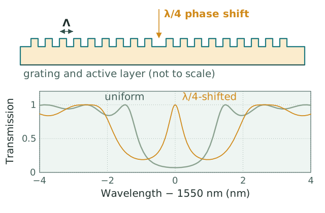
Top: a first-order grating of period with an extra half-period groove at its center, the quarter-wave phase shift. Bottom: computed transmission of the passive grating by coupled-mode theory ( nm, , also used as the group index, nm, µm, ). A uniform grating reflects across a band about 3.0 nm wide between its first zeros; its two equal-threshold modes sit just outside the 1.6 nm stop band (), one at each edge, and the phase shift opens a single resonance 0.6 nm wide at , which is where the λ/4-shifted laser oscillates.
A uniform grating with antireflection-coated facets does not lase at itself. Its reflection band, the stop band, has two modes of equal threshold at its edges, and the laser can run on either or on both. Two designs break the tie. The quarter-wave phase shift inserts an extra half period at the center of the grating, as in the figure, which opens a single resonance at in the middle of the stop band, where the competing modes get much less feedback; a λ/4-shifted DFB with antireflection coatings on both facets is single-mode almost regardless of fabrication detail, at the cost of emitting as much power from its rear facet as from its front. The alternative is a high-reflection coating on one facet and an antireflection coating on the other, which sends most of the power out of the front, but the grating's phase at the cleaved facet is random, so only a fraction of the devices from a wafer come out single-mode. A stronger grating concentrates the light near the phase shift, where it depletes the gain; this longitudinal spatial hole burning erodes the side-mode margin at high power, which is why designs keep moderate, around 1 to 1.5.
Typical specifications
| Parameter | Typical value for a telecom DFB |
|---|---|
| Threshold current | 5–20 mA |
| Side-mode suppression ratio | Above 35 dB; above 45 dB for higher grades |
| Linewidth | 1–10 MHz; below 1 MHz for long-cavity narrow-linewidth designs |
| Wavelength change with temperature, | 0.08–0.10 nm/°C |
| Wavelength change with current, | About 0.01 nm/mA |
| Output power | Up to about 100 mW in high-power butterfly modules |
| Wavelength range | 1270–1620 nm (O to L bands); GaAs-based devices near 760 nm and GaSb-based devices beyond 2 µm serve gas sensing |
The temperature coefficient is about a quarter of a Fabry-Perot laser's 0.4 nm/°C, because the grating rather than the gain peak sets the wavelength. It still matters for wavelength-division multiplexing: moving one 100 GHz channel (0.8 nm) takes about 9 °C, so a DWDM laser is held on its channel by a thermoelectric cooler, while uncooled DFBs serve coarse WDM, whose 20 nm channels tolerate the drift. Current tuning is what a gas analyzer uses to sweep across an absorption line. The Bragg Wavelength Calculator converts between grating period and emission wavelength, the DFB characterization workflow covers measuring the numbers in the table, and how to measure laser linewidth covers the linewidth in detail.
A single-mode laser is also sensitive to light returning into it. The reflection from an open connector drives a DFB into coherence collapse, and even the much weaker reflection of a mated connector changes its linewidth (optical feedback regimes works through the levels), which is why transmitter packages include an optical isolator and analog and PON links use angled connectors.
DFB, DBR and Fabry-Perot lasers
| Fabry-Perot | DFB | DBR | |
|---|---|---|---|
| Feedback | Cleaved facets | Grating along the gain section | Passive grating mirrors beside the gain section |
| Spectrum | Several longitudinal modes, about 1.1 nm apart at 1550 nm for a 300 µm chip | One mode, SMSR above 35 dB | One mode |
| Temperature tuning | About 0.4 nm/°C with the gain peak, in mode hops | 0.08–0.10 nm/°C, continuous | 0.08–0.10 nm/°C, like a DFB |
| Electronic tuning | None useful | Small, through the drive current | Several nm with three sections, part of it continuous; 40 nm and more with sampled gratings |
| Typical use | Short-reach links, pump lasers, low-cost sources | Fixed-wavelength transmitters, sensing | Tunable transmitters |
The Fabry-Perot mode spacing is , computed here at 1550 nm for a group index of 3.6; a multimode spectrum that wide spreads by dispersion over fiber and would overlap neighboring WDM channels, which is what the DFB's grating removes.
Uses
- Fiber-optic transmitters. Directly modulated DFBs serve short and medium reach; a DFB integrated with an electro-absorption modulator, the EML, serves longer reach and higher rates. DWDM transmitters use temperature-controlled DFBs on the channel grid, and a DFB array with a selector makes one kind of tunable laser. Coherent transceivers mostly use narrower-linewidth tunable lasers, since a MHz-class linewidth is too wide for most coherent formats.
- Continuous-wave sources for silicon photonics. An external laser source feeds the chip with one or more DFBs through polarization-maintaining fiber.
- Gas sensing. Tunable diode laser absorption spectroscopy sweeps a DFB's current across a molecular line, such as methane near 1654 nm or oxygen near 760 nm.
- DFB fiber lasers. The same principle in fiber: a phase-shifted fiber Bragg grating written in rare-earth-doped fiber and optically pumped forms a cavity a few centimeters long, with a far narrower linewidth than a semiconductor DFB, used in fiber sensing.
Common questions
What does DFB stand for?
Distributed feedback: the laser's feedback is distributed along the cavity by a grating, instead of being concentrated at two mirrors.
What is the difference between a DFB and a DBR laser?
Both use Bragg gratings. In a DFB the grating runs along the gain region; in a DBR it forms passive mirrors outside it, which can be tuned by current independently of the gain. DBR lasers therefore tune over several nanometers, and over 40 nm with sampled gratings, at the cost of more control currents and a linewidth that broadens as current is injected into the tuning sections.
What is the difference between a DFB laser and a Fabry-Perot laser?
A Fabry-Perot laser takes its feedback from its cleaved facets and runs on several longitudinal modes about a nanometer apart; the DFB's grating keeps one of them. The DFB costs more, but its single mode is what long-reach links and wavelength-division multiplexing need.
Why do DFB lasers have a quarter-wave phase shift?
A uniform grating has two equally favored modes at the edges of its stop band. The quarter-wave shift, an extra half period in the middle of the grating, places a single mode at the Bragg wavelength in the center of the stop band, so the laser is single-mode with high yield.
How is a DFB laser tuned?
By temperature, about 0.09 nm/°C, and by drive current, about 0.01 nm/mA, which heats the chip and changes its carrier density. A 60 °C change in chip temperature moves it about 5 nm: enough to set a DWDM channel or scan a gas line, not to tune across a band.
References: H. Kogelnik and C. V. Shank, "Coupled-wave theory of distributed feedback lasers," Journal of Applied Physics 43, 2327 (1972). G. P. Agrawal and N. K. Dutta, Semiconductor Lasers, 2nd ed. (Van Nostrand Reinhold, 1993). L. A. Coldren, S. W. Corzine and M. L. Mašanović, Diode Lasers and Photonic Integrated Circuits, 2nd ed. (Wiley, 2012).