Plasma dispersion effect (Soref-Bennett relations)
The change in refractive index and absorption of a semiconductor produced by a change in its free-carrier density: adding electrons or holes lowers the index and raises the loss. In silicon it is the only electro-optic effect strong enough to build modulators on, and the Soref-Bennett relations, Δn = −(8.8×10⁻²² ΔN + 8.5×10⁻¹⁸ ΔP^0.8) and Δα = 8.5×10⁻¹⁸ ΔN + 6.0×10⁻¹⁸ ΔP at 1550 nm, quantify it.
The plasma dispersion effect is the modification of the refractive index and absorption coefficient of a semiconductor by a change in its free-carrier density. Electrons and holes respond to an optical field as a plasma: they add a negative contribution to the real index, so more carriers mean a lower index, and their scattering absorbs light, so more carriers mean more free-carrier absorption. The two changes are linked by the Kramers-Kronig relations and cannot be had separately, which is the central fact of silicon modulator design. The Plasma Dispersion Calculator evaluates the relations below for any electron and hole density and turns them into phase shift, loss, and the length for π.
The Soref-Bennett relations
Soref and Bennett assembled the measured absorption spectra of doped silicon, applied a Kramers-Kronig transform to obtain the index change, and fitted the results at the two telecom wavelengths. With and the electron and hole densities in cm⁻³, dimensionless and in cm⁻¹, at 1550 nm
and at 1310 nm
Nedeljkovic, Soref and Mashanovich repeated the analysis in 2011 with newer absorption data and power-law fits for both carriers, extending it from 1.3 to 14 µm; at 1550 nm their fit is and , which agrees with the 1987 relations within 15 % at 10¹⁸ cm⁻³, and at 2 µm their fits give 1.6 to 1.7 times the 1550 nm values at 10¹⁸ cm⁻³. Because the fits come from dopant absorption, they apply equally to carriers introduced by doping, injection or depletion. The tool carries all four sets.
| Carriers, 1550 nm | Length for π | Loss over that length | ||
|---|---|---|---|---|
| 10¹⁷ electrons | −8.8 × 10⁻⁵ | 0.85 cm⁻¹ (3.7 dB/cm) | 8.8 mm | 3.3 dB |
| 10¹⁷ holes | −3.4 × 10⁻⁴ | 0.60 cm⁻¹ (2.6 dB/cm) | 2.3 mm | 0.60 dB |
| 10¹⁸ electrons | −8.8 × 10⁻⁴ | 8.5 cm⁻¹ (37 dB/cm) | 881 µm | 3.3 dB |
| 10¹⁸ holes | −2.1 × 10⁻³ | 6.0 cm⁻¹ (26 dB/cm) | 363 µm | 0.95 dB |
| 10¹⁸ electrons and holes | −3.0 × 10⁻³ | 14.5 cm⁻¹ (63 dB/cm) | 257 µm | 1.6 dB |
| 5 × 10¹⁷ electrons and holes | −1.7 × 10⁻³ | 7.3 cm⁻¹ (31 dB/cm) | 465 µm | 1.5 dB |
The lengths assume the whole mode sees the carrier change; a real phase shifter multiplies by the overlap of the mode with the modulated region, which is near one for injection into the whole core and 0.1 to 0.4 for the depleted slice of a pn junction, and the length for π grows by while the loss over it does not change. Two features of the table drive design. Holes are the better phase shifter: at 10¹⁸ cm⁻³ they give 2.4 times the index change of electrons for 0.7 times the absorption, so a π shift costs 0.95 dB with holes against 3.3 dB with electrons, and the electron figure is the same at every density because both electron terms are linear. This is why depletion modulators are usually built with the junction offset so that more of the mode sits in the p-doped side. And the index change at practical densities is a few times 10⁻³, a hundred times the Kerr effect but still small, so silicon phase shifters are millimeters long and the loss of the doping itself, 2 to 4 dB/cm at 10¹⁷ cm⁻³, is a permanent part of the insertion loss.
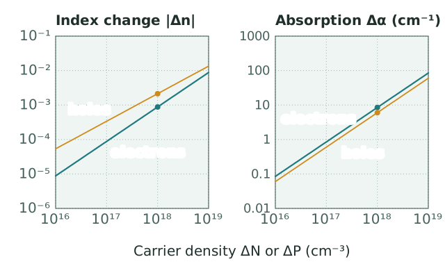
Index and absorption changes of silicon at 1550 nm from the Soref-Bennett relations, for electrons alone and holes alone; the dots mark 10¹⁸ cm⁻³. Because the hole index term grows as , the advantage of holes narrows with density, from 3.8 times the electron value at 10¹⁷ cm⁻³ to 2.4 times at 10¹⁸ cm⁻³.
Why silicon uses it
Silicon is centrosymmetric and has no Pockels effect. The Kerr effect gives at the largest fields a junction survives, and the Franz-Keldysh effect is weak at 1550 nm, far below the band edge. The thermo-optic effect, per kelvin, is strong but microsecond-slow and dissipative. Plasma dispersion is the only mechanism in silicon that gives an index change of order 10⁻³ at gigahertz speeds, and every silicon Mach-Zehnder and ring modulator in production uses it, at the price of the absorption that comes with it.
Modulator architectures
| Architecture | Mechanism | Bandwidth | Insertion loss | |
|---|---|---|---|---|
| Carrier injection, forward-biased p-i-n | Carriers injected into the intrinsic core | 0.01 to 0.1 V·cm, loosely defined since the phase follows current | limited by carrier lifetime: a corner near 160 MHz for a 1 ns lifetime, gigabits per second only with pre-emphasis | 2 to 5 dB |
| Carrier depletion, reverse-biased pn | Depletion width swept through the mode | 1 to 3 V·cm | 30 to 60 GHz | 3 to 7 dB |
| Carrier accumulation, MOS capacitor | Charge accumulated at a thin oxide in the core | 0.05 to 0.5 V·cm | 10 to 30 GHz, RC-limited | 3 to 6 dB |
| Ring resonator with any of the above | Same , resonance shift read as amplitude | not applicable; 10 to 50 pm/V | 30 to 60 GHz, photon-lifetime-limited | 1 to 3 dB plus the ring's own loss |
Carrier injection reaches the largest carrier densities and the smallest , but removing the carriers takes the recombination time, so it is used for switches and slow phase trimming rather than data modulation. Depletion trades efficiency for speed: the depletion width changes as the square root of the reverse bias, the phase is nonlinear in voltage, and the half-wave voltage times length of 1 to 3 V·cm is an order of magnitude worse than injection, but the response follows the junction capacitance rather than a lifetime. The MOS capacitor, introduced by Liu and colleagues at Intel in 2004 for the first gigahertz silicon modulator, accumulates carriers on both sides of a thin gate oxide inside the waveguide and sits between the two in efficiency and speed.
Other materials
Germanium has the same effect with larger coefficients in the mid-infrared, which Nedeljkovic and colleagues fitted separately, and germanium-on-silicon modulators combine it with the Franz-Keldysh effect in electro-absorption modulators. III-V semiconductors show plasma dispersion as well, but InP and GaAs modulators lean on the Pockels and quantum-confined Stark effects and treat the carrier contribution as a correction. Where a silicon platform needs a loss-free phase shifter it bonds a Pockels material on top, thin-film lithium niobate or barium titanate, and leaves plasma dispersion for the ring tuners and the switches.
References: R. A. Soref and B. R. Bennett, "Electrooptical effects in silicon," IEEE Journal of Quantum Electronics 23, 123 (1987). M. Nedeljkovic, R. Soref, and G. Z. Mashanovich, "Free-carrier electrorefraction and electroabsorption modulation predictions for silicon over the 1-14-μm infrared wavelength range," IEEE Photonics Journal 3, 1171 (2011). M. Nedeljkovic, R. Soref, and G. Z. Mashanovich, "Predictions of free-carrier electroabsorption and electrorefraction in germanium," IEEE Photonics Journal 7, 2600214 (2015). G. T. Reed, G. Mashanovich, F. Y. Gardes, and D. J. Thomson, "Silicon optical modulators," Nature Photonics 4, 518 (2010). A. Liu et al., "A high-speed silicon optical modulator based on a metal-oxide-semiconductor capacitor," Nature 427, 615 (2004). G. T. Reed and A. P. Knights, Silicon Photonics: An Introduction (Wiley, 2004), chapter 5.