Mach-Zehnder modulator (MZM)
An intensity modulator built from a Mach-Zehnder interferometer with an electro-optic phase shifter in one or both arms: the drive voltage sets the phase difference and the output follows cos²(Δφ/2). It is the modulator behind every coherent transceiver and many 100G-and-up direct-detect links. How it works, the half-wave voltage and what sets it on each material platform, bias points, chirp, extinction ratio, and the IQ modulator built from two of them.
A Mach-Zehnder modulator splits the incoming light into two waveguide arms, shifts the optical phase in one or both of them with an applied voltage, and recombines the arms so that the two fields interfere. With a phase difference between the arms the transmitted power is
so equal phases give full transmission, a difference of π gives extinction, and the voltage that produces that π is the half-wave voltage . Everything else about the device follows from that cosine: where it is biased, how linear it is, how much chirp it imposes, and how the phase shifter's physics sets the drive voltage and the bandwidth.
The half-wave voltage
In a Pockels material such as lithium niobate the index change is linear in the field, , and for an electrode gap and length the half-wave voltage is
with the overlap of the applied field with the optical mode. Since scales as , the product is the figure of merit of the phase shifter, and the platforms differ in it by an order of magnitude.
| Platform | Mechanism | Typical | Notes |
|---|---|---|---|
| Bulk lithium niobate, titanium-diffused | Pockels effect, linear | 5 – 15 V·cm | 5 to 10 cm long; the long-haul standard for three decades |
| Thin-film lithium niobate | Pockels, linear | 1.5 – 3 V·cm | sub-micron mode lets the electrodes close in; 100 GHz demonstrated |
| Silicon, carrier depletion | Plasma dispersion, nonlinear in V | 1 – 3 V·cm | phase comes with absorption; 3 to 6 dB loss |
| InP multi-quantum-well | Quantum-confined Stark effect plus Pockels | 0.3 – 1 V·cm | a few millimeters long, integrated with the laser |
| Electro-optic polymer | Pockels, linear | 0.5 – 2 V·cm | very high ; stability under heat and light is the question |
| Barium titanate on silicon | Pockels, linear | 0.2 – 0.5 V·cm | the largest coefficient of any thin film |
The Vπ measurement article covers the bias-sweep measurement, and the Vπ Fitter extracts , the extinction ratio and the quadrature point from a pasted sweep. Silicon's phase shift is the one case where the cosine is fed by a nonlinear phase: depletion width grows as the square root of the reverse bias, so depends on where the swing sits, and the Plasma Dispersion Calculator turns a carrier-density swing into the phase and the loss it brings.
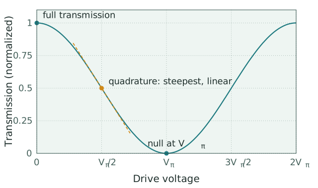
The ideal transfer curve of a push-pull modulator. The dashed line is the slope at quadrature, where a small drive swing maps linearly onto intensity. The Vπ Fitter fits this curve to a measured bias sweep.
Bias point, linearity and chirp
The modulator is operated about a bias point set by a slow DC voltage on a separate electrode or a thermal phase tuner. At quadrature, , the transfer curve is steepest and locally linear, which is the bias for analog links and for the small-signal measurements that characterize the device; the third-order distortion of the cosine then sets the spurious-free dynamic range. For on-off keying the swing runs from near the minimum to near the maximum, a full of drive, and the flat regions at both ends compress the eye's noise. For phase-shift keying the bias is the null, , and the drive swings through it: the output field changes sign as it passes the null, which is a π phase flip with the amplitude momentarily at zero, and that is how a Mach-Zehnder makes a binary phase modulator without any optical phase reference. Driving the two arms in push-pull, with equal and opposite voltages, halves the swing each arm sees and cancels the phase modulation of the output: the fields in the two arms shift by , their sum changes amplitude but not phase, and the modulator is chirp-free. A single-arm drive imposes a chirp with an alpha parameter of order one, which interacts with fiber dispersion; a deliberately unbalanced push-pull sets a small negative chirp that extends the reach of 10 Gb/s links over standard fiber. Silicon modulators, whose phase and loss change together, carry a residual chirp even in push-pull.
Extinction ratio and loss
Complete extinction needs equal amplitudes in the two arms at the combiner. With a power ratio between the arms the extinction ratio is : a 0.5 dB imbalance limits it to 31 dB, a 1 dB imbalance to 25 dB, and a 2 dB imbalance to 19 dB. Lithium niobate devices reach 25 to 35 dB because their splitters are balanced and their arms lossless; silicon devices land at 20 to 30 dB because the doped phase shifters absorb, and the absorption changes with the drive. Insertion loss is 3 to 5 dB for a packaged lithium niobate modulator including the fiber coupling, 3 to 7 dB for thin-film lithium niobate, and 4 to 8 dB for silicon, of which the doping and the junction account for half.
Bandwidth
A short phase shifter is a lumped capacitor and its bandwidth is RC-limited; a long one is a transmission line, and the electrical wave must travel with the optical wave for the phase to accumulate coherently. Traveling-wave electrodes on lithium niobate are designed so that the microwave index matches the optical group index of about 2.2, which on bulk lithium niobate, where the microwave index is naturally near 4, takes thick electrodes and a buffer layer; on thin-film lithium niobate the mismatch is small and 100 GHz devices a few centimeters long have been demonstrated, with electrode loss rather than velocity mismatch setting the limit. Silicon depletion modulators reach 40 to 60 GHz with traveling-wave electrodes loaded by the junction capacitance, and InP devices reach similar figures in a few millimeters. The modulation bandwidth entry covers the measurement.
The IQ modulator
Two Mach-Zehnder modulators in the arms of a third interferometer, each biased at its null and the pair combined in quadrature, form the IQ modulator: one child modulates the in-phase component of the field, the other the quadrature component, and any point in the complex plane can be reached. Every coherent transceiver drives one, or two for the two polarizations, with four-level or higher electrical signals to produce QPSK, 16-QAM or 64-QAM, and the chirp-free, linear response of the lithium niobate or thin-film lithium niobate version is why those platforms own the long-haul market while silicon serves the shorter, intensity-modulated links inside the datacenter.
References: E. L. Wooten et al., "A review of lithium niobate modulators for fiber-optic communications systems," IEEE Journal of Selected Topics in Quantum Electronics 6, 69 (2000). C. Wang et al., "Integrated lithium niobate electro-optic modulators operating at CMOS-compatible voltages," Nature 562, 101 (2018). G. T. Reed, G. Mashanovich, F. Y. Gardes, and D. J. Thomson, "Silicon optical modulators," Nature Photonics 4, 518 (2010). F. Koyama and K. Iga, "Frequency chirping in external modulators," Journal of Lightwave Technology 6, 87 (1988). S. Abel et al., "Large Pockels effect in micro- and nanostructured barium titanate integrated on silicon," Nature Materials 18, 42 (2019).