Acceptance angle
The largest angle to the fiber axis at which light entering the end face of an optical fiber is guided: sin θ = NA in air. Standard single-mode fiber accepts light within 7.1° of its axis (index-step NA 0.123; its far-field datasheet NA of 0.14 gives 8.0°), 50 µm multimode fiber (NA 0.20) within 11.5° and 62.5 µm multimode fiber (NA 0.275) within 16.0°.
The acceptance angle of an optical fiber is the largest angle, measured from the fiber axis, at which a ray entering the end face is guided along the core. It is set by the numerical aperture:
where is the index of the medium in front of the fiber, 1 for air. Standard single-mode fiber, with the NA of its 0.36% index step, 0.123, accepts light within 7.1° of its axis, a full cone of 14.1°; the NA of 0.14 on its datasheet is measured from the far field of the guided mode and would give 8.0° and 16.1°. 50 µm multimode fiber, at NA 0.20, accepts 11.5°, and 62.5 µm multimode fiber, at NA 0.275, accepts 16.0°. Rays outside the cone meet the core-cladding boundary at less than the critical angle and leave the core within a short distance. The Fiber Numerical Aperture and V Number Calculator draws the cone for any NA and launch medium.
Where the formula comes from
A ray entering the end face at an angle to the axis refracts toward the axis, to an angle given by Snell's law, , and then meets the core-cladding boundary at from the boundary's normal. It is guided by total internal reflection if that angle is at least the critical angle , where . At the limit , and
The acceptance angle and the critical angle therefore describe the same limiting ray at two surfaces: the acceptance angle outside the end face, measured from the axis, and the critical angle at the core-cladding boundary, measured from its normal. For the small index steps of telecom fiber, NA ≈ with : a core of index 1.4500 in a cladding of 1.4440 gives NA 0.132 and an acceptance angle of 7.6° in air.
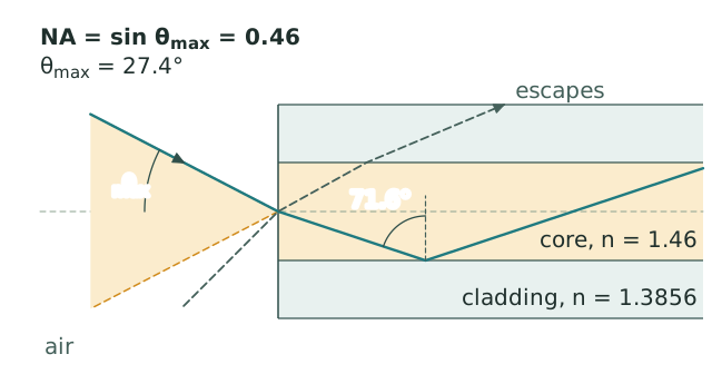
Acceptance cone drawn to scale for and NA = 0.46 (), the double-clad row of the table below. The ray at ° refracts to 18.4° inside the core and meets the boundary at the critical angle, 71.6° from the normal; a ray entering at 45° meets it at 61.0° and leaves through the cladding.
Because NA is , the numerical aperture stays the same when the medium in front of the fiber changes, but the acceptance angle does not: in water ( = 1.333), standard single-mode fiber at its datasheet NA of 0.14 accepts 6.0° instead of 8.0°.
Values for common fibers
| Fiber | NA | Acceptance half-angle in air | Full cone |
|---|---|---|---|
| Standard single-mode, ITU-T G.652 (SMF-28), far-field specification | 0.14 | 8.0° | 16.1° |
| The same fiber, from its 0.36% index step | 0.123 | 7.1° | 14.1° |
| 50/125 µm graded-index multimode (OM2 to OM5) | 0.200 | 11.5° on the core axis | 23.1° |
| 62.5/125 µm graded-index multimode (OM1) | 0.275 | 16.0° on the core axis | 31.9° |
| 105/125 µm step-index multimode | 0.22 | 12.7° | 25.4° |
| Double-clad fiber, inner cladding | 0.46 | 27.4° | 54.8° |
For single-mode fiber the angle is not a sharp limit. The guided mode's far field is close to Gaussian, with a half-angle of 5.2° at 1310 nm and 5.4° at 1550 nm, and the specified NA of 0.14 is the sine of the angle at which the far field has fallen to 1% of its peak (the numerical aperture entry works through this). The index step gives a lower value, 0.123 for the 0.36% step of SMF-28, and that is the figure that enters the V number. Coupling into a single-mode fiber depends on how well the incoming beam matches the mode in size, position and direction rather than on the cone: a beam matched in size but tilted by 2.6° against the axis of a fiber with a 10.4 µm mode field diameter loses 1 dB (mode mismatch loss), well inside the nominal 8°.
Graded-index fibers
In a graded-index fiber the core index falls from the axis to the cladding, so the acceptance angle depends on where the light enters. The local numerical aperture is , and for the near-parabolic profile of multimode telecom fiber
for a core of radius . In a 50 µm fiber with NA 0.20 on the axis, light entering halfway to the edge of the core is accepted within 10.0°, and at 90% of the radius within 5.0°. Averaged over the core, a graded-index fiber accepts half as much light from a uniform, wide-angle source that fills its core as a step-index fiber with the same NA on the axis.
Skew rays
The derivation above follows meridional rays, which pass through the fiber axis. Skew rays, which enter off the axis and spiral around it without crossing it, meet the core-cladding boundary more obliquely than a meridional ray at the same angle to the axis, so some of them are trapped at angles beyond . Part of this light travels as leaky, or tunneling, rays that lose power along the fiber, which is one reason a short, fully filled step-index fiber shows some light outside its nominal cone (Snyder and Love).
Coupling light into and out of a fiber
For multimode fiber, the acceptance angle and the core size together set how much of a source's light can be coupled. A lens can shrink the image of a source only by widening its cone, since the product of spot radius and NA, the one-dimensional étendue, is conserved through lossless optics; a source is coupled without loss only if its image fits inside the core while its cone stays inside the acceptance angle. A source smaller than the core that emits over a hemisphere with a Lambertian distribution, such as a surface-emitting LED, puts a fraction of its power into the acceptance cone of a step-index fiber in air: 4.0% at NA 0.20 (−14.0 dB), 7.6% at 0.275 (−11.2 dB) and 21% at 0.46 (−6.7 dB). A further 3.4% (0.15 dB) is reflected at an uncoated silica end face (Fresnel equations).
For single-mode fiber, the lens is chosen to reproduce the fiber's mode, not to fill its cone; Coupling a Free-Space Beam into Single-Mode Fiber gives the procedure and tolerances, and the Fiber Coupling Efficiency Calculator computes the overlap for given mode sizes and offsets.
The same angle describes the light that leaves a fiber. A short, fully filled multimode fiber emits into a cone close to its acceptance angle; a long or tightly routed one emits into a narrower cone, because the high-order modes, which travel at the largest angles, are the first to be lost at bends and microbends (bend loss). The acceptance angle is therefore measured, like the numerical aperture, from the far field of a short, overfilled sample, as the half-angle at which the intensity falls to a set fraction of its peak; a lower fraction gives a wider angle from the same fiber, so two values compare only at the same fraction.
In high-contrast chip waveguides the formula gives an NA above 1, which means that every ray arriving from air is accepted. Coupling to them is limited by the size of the guided mode instead, which edge couplers expand to meet the fiber.
Common questions
What is the acceptance angle of an optical fiber?
The largest angle to the fiber axis at which light entering the end face is guided by total internal reflection, in air. Light within this cone is guided; light outside it leaves the core.
How is the acceptance angle calculated?
From the core and cladding indices, , or from the specified numerical aperture, . A core of index 1.4500 in a cladding of 1.4440 gives NA 0.132 and 7.6° in air; a fiber specified at NA 0.22 accepts 12.7°.
What is the difference between the acceptance angle and the critical angle?
They describe the same limiting ray at two surfaces. The acceptance angle is measured outside the end face, from the fiber axis; the critical angle is measured at the core-cladding boundary, from its normal. They are related by .
What is the acceptance angle of single-mode fiber?
Standard single-mode fiber is specified at NA 0.14, an acceptance angle of 8.0° in air, measured where the far field falls to 1% of its peak. Its mode has no sharp edge, and coupling into it depends on matching the mode's size and direction: a tilt of 2.6° already costs 1 dB at 1550 nm.
What happens to light outside the acceptance angle?
It meets the core-cladding boundary at less than the critical angle, so it is partly transmitted at every reflection and leaves the core within a short distance, into the cladding and the coating. Some skew rays beyond the angle are trapped for a while as leaky rays and are lost more slowly.
References: B. E. A. Saleh and M. C. Teich, Fundamentals of Photonics, 3rd ed. (Wiley, 2019), chapters on ray optics and fiber optics. A. W. Snyder and J. D. Love, Optical Waveguide Theory (Chapman and Hall, 1983). J. M. Senior, Optical Fiber Communications: Principles and Practice, 3rd ed. (Prentice Hall, 2009). Corning, SMF-28 Ultra Optical Fiber product information sheet (NA and refractive index difference). IEC 60793-2-10, sectional specification for category A1 multimode fibres (50 and 62.5 µm NA values). IEC 60793-1-43, Optical fibres, Part 1-43: Measurement methods and test procedures, numerical aperture.