Balanced detection
A photodetection scheme using two photodiodes with the difference of their photocurrents taken as the output. Cancels common-mode signals and noise, doubling sensitivity for coherent detection.
A balanced photodetector consists of two photodiodes in series (or with their outputs subtracted electronically). Signal is split equally between the two diodes via an optical hybrid or 2×2 coupler; the photocurrents are subtracted:
For coherent detection, the optical hybrid divides the input as:
The difference cancels the large DC LO offset and doubles the beat signal:
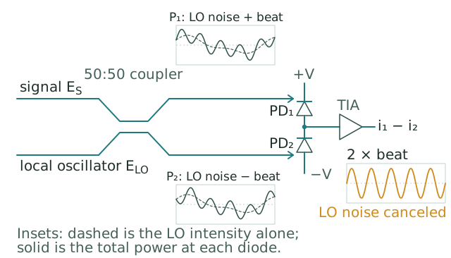
The coupler delivers the local-oscillator intensity noise to both diodes with the same sign and the signal beat with opposite signs, so the difference current carries twice the beat and none of the common-mode noise. The two photodiodes are in series and reverse biased, and their junction feeds the transimpedance amplifier.
Why balance helps.
| Noise/signal source | Single-detector | Balanced |
|---|---|---|
| Coherent beat signal | ; doubled | |
| LO intensity noise (common-mode) | Limits sensitivity | Canceled to first order |
| LO RIN | Adds to noise floor | Canceled to first order |
| Detector dark current | Adds noise | Both detectors contribute, but signal also doubled |
| Detector shot noise | (twice the photons, but added in quadrature) |
The 3 dB SNR improvement comes from: signal doubling (6 dB) minus shot noise doubling (3 dB) = 3 dB net.
Critical hybrid balance. Balanced detection works only when the optical hybrid splits signal and LO with high common-mode rejection; where the rejection comes from, how it falls with frequency, and how to measure it are covered in Common-mode rejection in balanced detectors. Typical commercial balanced detectors specify 25 – 30 dB common-mode rejection ratio (CMRR) at the operating wavelength. Below this, residual imbalance leaves LO intensity noise contaminating the output.
Applications.
| Use case | Why balanced |
|---|---|
| Coherent telecom receivers | Standard architecture for QPSK and higher-order coherent reception |
| Optical homodyne measurement | LO RIN suppression is essential for shot-noise-limited detection |
| RIN measurement | Self-balanced configurations measure laser RIN by canceling correlated noise |
| OCT (swept-source) | LO from reference arm, signal from sample arm; balanced detection rejects LO sweep-induced fluctuations |
| Quantum-noise-limited measurements | Required for sub-shot-noise quantum metrology |
Practical balanced detectors are commonly packaged with both diodes on a single substrate, with closely-matched responsivity and bandwidth, and integrated transimpedance amplifiers operating in differential mode. Modern coherent telecom transceivers integrate four balanced detector pairs (in-phase and quadrature, for two polarizations) into a single silicon photonic IC.
The balanced detection scheme is to coherent receivers what differential signaling is to high-speed digital electronics. Common-mode noise rejection is the architectural advantage in both cases.