Characteristic Temperature Extraction from LIV Measurements
Procedure for extracting the characteristic temperature T₀ of a semiconductor laser diode from temperature-dependent threshold current measurements, with worked example and discussion of extraction errors.
Scope
This article describes the procedure for extracting the characteristic temperature of a semiconductor laser diode from light–current–voltage (LIV) measurements taken at multiple heatsink temperatures. The procedure assumes single-mode or near-single-mode lasing behavior and continuous-wave or low-duty-cycle pulsed operation. Application to gain-switched or mode-locked devices is outside scope.
Definition
The threshold current of a semiconductor laser depends on the active region temperature through the empirical relation
where is a temperature-independent pre-exponential constant with units of current and is the characteristic temperature in kelvin. The parameter quantifies the temperature sensitivity of the threshold current: smaller corresponds to stronger temperature dependence.
Representative values for common laser systems are summarized below.
| Material system | Wavelength range | Typical |
|---|---|---|
| AlGaAs / GaAs | 750–850 nm | 120–160 K |
| InGaAs / GaAs | 900–1100 nm | 100–140 K |
| InGaAsP / InP | 1300–1550 nm | 50–70 K |
| InGaAlAs / InP | 1300–1550 nm | 70–90 K |
| GaN / InGaN | 405–470 nm | 90–150 K |
A second characteristic temperature describing the temperature dependence of the differential quantum efficiency is sometimes reported alongside . Extraction of requires the same dataset but is treated separately and is not covered here.
Required measurements
Extraction requires LIV sweeps at distinct heatsink temperatures, spanning at least 30 K and ideally 40–60 K, with extracted from each sweep by a consistent method.
The hardware configuration is:
| Function | Component | Specification |
|---|---|---|
| Current source | SMU or pulse generator | Compliance current ; resolution of |
| Voltage measurement | 4-wire Kelvin sense | μV resolution |
| Optical power | Calibrated photodetector | Linear range covering 5 decades above noise floor |
| Temperature control | TEC + thermistor close to submount | K stability, NTC thermistor or PT100 RTD |
| Mounting | Thermally conductive submount | AlN or CuW preferred for high-power devices |
Heatsink temperature is set via a closed-loop TEC controller (Newport 350B, Thorlabs TED200C, or equivalent). The thermistor must be placed within 1 mm of the submount to minimize the offset between measured temperature and true heatsink temperature.
Threshold extraction method
Inconsistent threshold extraction across temperatures is the dominant source of error in values reported in the literature. The threshold definition must be fixed before any LIV sweeps are taken and applied identically at every temperature.
The two-segment linear fit is the recommended method for typical diode laser LIV data. The procedure:
- Identify the lasing region of the LIV curve as the range where .
- Fit a linear function to this region.
- Identify the sub-threshold region.
- Fit a linear function to the sub-threshold region.
- The intersection of the two fits is .
Alternative methods include the second-derivative peak ( maximum), the inflection point of vs. , and the current at a fixed output power. These methods do not produce equivalent values and must not be mixed within a single extraction.
Extraction procedure
1. Measurement
Acquire LIV sweeps at heatsink temperatures. Recommended range: 5–10 K below room temperature to 30–50 K above. In continuous-wave sweeps, self-heating raises the junction above the heatsink temperature and bends the curve at high currents, which shifts the extracted ; fits confined to the range just above threshold keep the shift small (see Pulsed versus Continuous-Wave LIV Measurement). Pulsed operation (typical: 1 μs pulse width, 0.1% duty cycle) is preferred for high-power devices.
2. Threshold extraction
Apply the chosen threshold extraction method (see above) to each LIV curve, producing the dataset .
3. Linearization
Taking the natural logarithm of both sides of the threshold relation gives
which is linear in with slope and intercept .
4. Fit
Perform a least-squares linear fit on versus . The slope yields . The intercept yields .
The fit residuals should be examined. Systematic curvature in the residuals indicates either (a) deviation from the simple exponential model, often at temperatures approaching thermal rollover, or (b) inconsistent threshold extraction across temperatures.
Worked example
The following illustrative dataset is for a 1310 nm Fabry–Pérot InP laser die with a high-reflection coating on its rear facet, with the power taken from the front facet, at five heatsink temperatures. It is measured pulsed, with 1 μs pulses at 0.1% duty cycle, so that the junction stays close to the heatsink temperature.
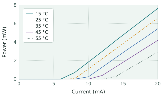
Two-segment linear fit extraction yields:
| (K) | (mA) | |
|---|---|---|
| 288.15 | 6.8 | 1.9169 |
| 298.15 | 8.0 | 2.0794 |
| 308.15 | 9.5 | 2.2513 |
| 318.15 | 11.2 | 2.4159 |
| 328.15 | 13.3 | 2.5878 |
Least-squares fit of vs. produces a slope of K and intercept of (). The extracted parameters are
The small is expected: it is the extrapolated pre-exponential at K, not a physically reachable operating current, and for a low- device the exponential factor at room temperature is large ().
This value is consistent with the literature range for 1310 nm InGaAsP Fabry–Pérot devices ( K).
For interactive extraction from user data, see the T₀ Extraction Calculator.
Sources of extraction error
The following errors account for the majority of discrepancies between extracted and true values.
Inconsistent threshold definition. Switching extraction methods across temperatures introduces systematic error proportional to the temperature dependence of the method-to-method offset. Magnitude: 5–20% error in .
Self-heating during CW sweeps. Dissipated power raises the active region above the heatsink temperature, slightly at threshold and by several kelvin at high currents in poorly cooled or high-power devices. The threshold measured "at heatsink temperature " therefore corresponds to a higher junction temperature, and the difference grows with because does, biasing low. Its size depends on the thermal resistance: measured CW, with the thermal resistance used in the pulsed and CW comparison, the laser of the worked example would have its junction 0.3 K above the heatsink at threshold at 15 °C and 0.7 K at 55 °C, which would lower the extracted by about 1%. Fits that extend to high currents add a second error by tilting the lasing line. Pulsed operation at duty cycle largely removes both.
Insufficient temperature range. Two-point extractions and extractions over K of temperature range produce values dominated by single-point noise. Minimum five points over K is recommended.
Thermistor placement error. Thermistors located on the heatsink rather than the submount underestimate the true device temperature, particularly during high-current operation. The offset is approximately constant if measurement protocol is consistent and does not strongly bias ; absolute values may be affected.
Non-Arrhenius behavior at high . Near the thermal rollover regime, additional non-radiative loss mechanisms produce super-exponential threshold growth. The simple exponential model breaks down. The fit must be restricted to the temperature range where residuals are randomly distributed.
Mode hopping or filamentation between temperatures. In multi-transverse-mode or unstable devices, the lasing mode structure can shift between temperature setpoints, producing discontinuities in that are not captured by the simple exponential model.
Validation
Two checks indicate whether the extracted is reliable.
The fit residuals should be randomly distributed around zero with no systematic trend versus . Curvature, monotonic trend, or grouping in the residuals indicates a model failure or extraction inconsistency.
The extracted should fall within the literature range for the material system and device structure (see table above). Values outside the expected range by more than 20% almost certainly indicate extraction error rather than novel device physics.
References
For the original phenomenological derivation of the threshold current relation, see Pankove (1971). For modern semiconductor laser physics including the microscopic origin of , see Coldren, Corzine, and Mašanović (2012), chapter 5. For temperature dependence in long-wavelength InGaAsP/InP devices specifically, see Agrawal and Dutta (1993), chapter 3.